A complete engineering framework for selecting the right power cable — covering voltage rating, application scenario, installation environment, conductor sizing, and international compliance standards.
Voltage rating is the most fundamental parameter in cable selection. Using a cable with an insufficient voltage rating is the most dangerous and most common mistake in electrical engineering.
Every power cable is designed and tested to withstand a specific maximum operating voltage. This rating reflects the dielectric strength of the insulation material — the maximum electric field the insulation can sustain without breakdown. Operating a cable above its rated voltage causes accelerated insulation degradation, partial discharge, and ultimately catastrophic failure.
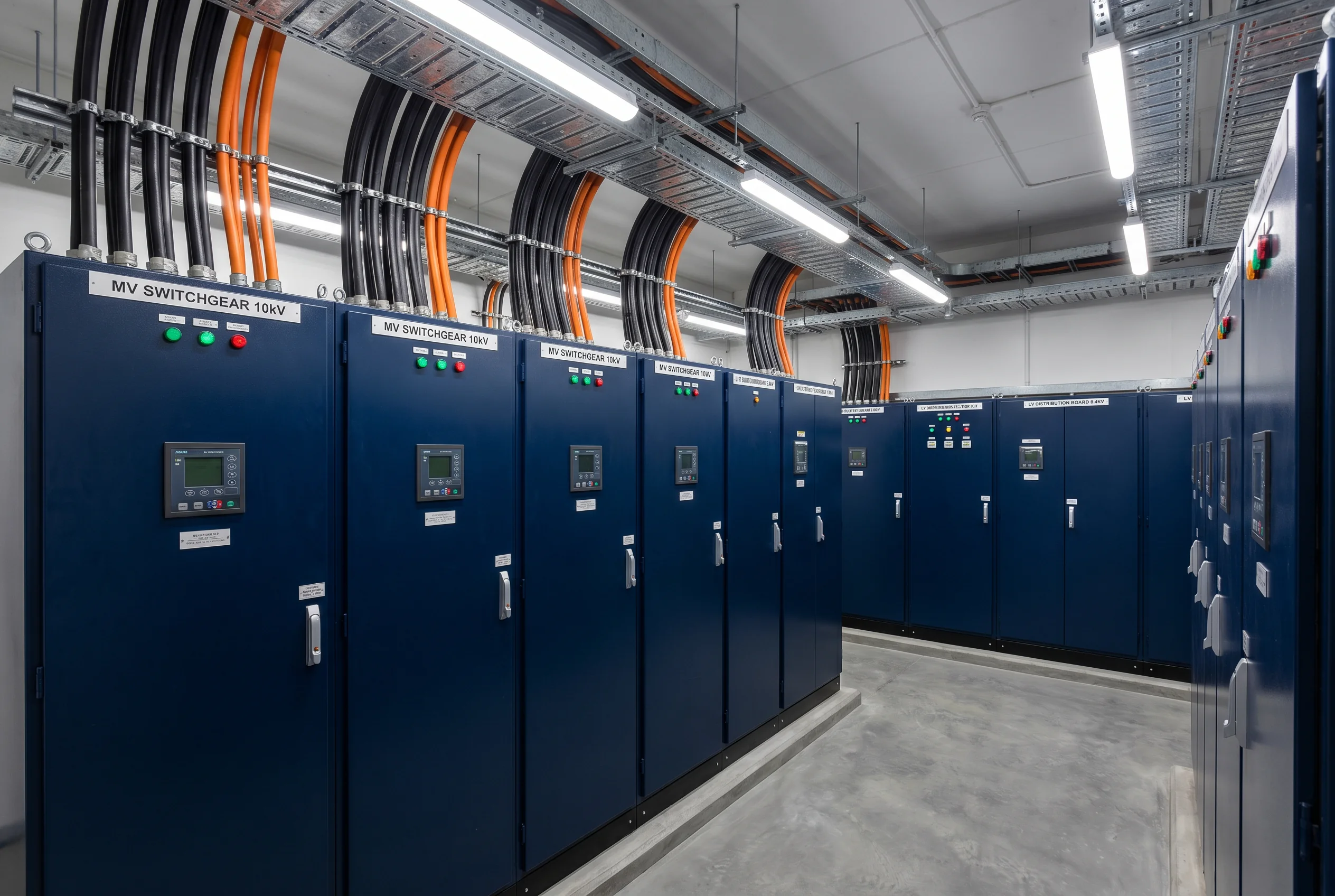
The rated voltage of a cable is expressed as U₀/U (kV), where U₀ is the conductor-to-earth voltage and U is the conductor-to-conductor voltage. For example, a 6/10kV cable is rated for 6kV phase-to-earth and 10kV phase-to-phase — suitable for a 10kV distribution system.
Always select a cable whose rated voltage is equal to or greater than the system operating voltage. Never downgrade. Always verify both U₀ and U values match the system design.
Building electrical systems, commercial facilities, light industrial equipment, motor feeders. The most widely deployed cable category globally.
Primary distribution in industrial parks, large commercial complexes, campus networks, and utility infrastructure. Requires specialized installation and termination expertise.
Transmission networks, offshore wind farm export cables, and inter-city grid connections. Requires specialist engineering and contractor qualification.
The deployment scenario determines which performance characteristics are mandatory. Fire safety, chemical resistance, UV protection, and explosion-proof ratings are not optional features — they are engineering requirements defined by the operating environment.
Each deployment environment imposes a unique combination of electrical, mechanical, thermal, and chemical stresses on the cable. The table below maps the most common scenarios to their required cable type and the engineering rationale behind each selection.
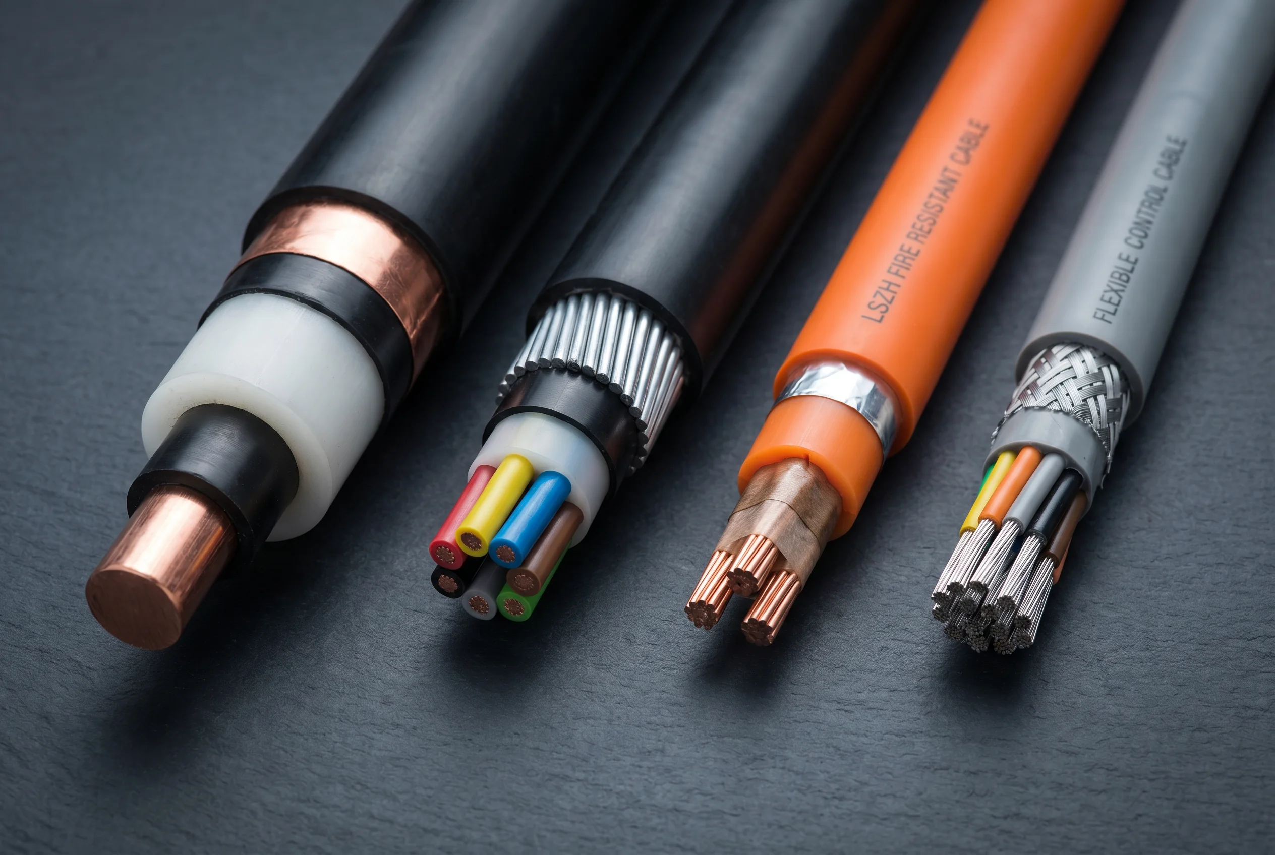
In a densely populated server environment, PVC cables produce toxic halogen gases when burning. LSZH (Low Smoke Zero Halogen) cables minimize smoke and toxic emissions, protecting both personnel and sensitive electronics. Shielding prevents EMI from UPS inverters and PDUs.
Life-support systems and operating theatres require uninterrupted power even during a fire event. Fire-resistant cables (IEC 60331) maintain circuit integrity at 750°C–950°C for 90–180 minutes, ensuring evacuation lighting, medical equipment, and emergency systems remain operational.
Factory floors expose cables to mechanical impact, crushing from vehicles, oil and coolant contamination, and rodent damage. Steel wire armored (SWA) or steel tape armored (STA) cables with oil-resistant PVC or HDPE sheaths provide the necessary mechanical and chemical protection.
Photovoltaic installations expose cables to continuous UV radiation, elevated operating temperatures (up to 120°C), and DC voltage with no zero-crossing. Standard PVC cables degrade rapidly outdoors. PV cables use cross-linked polyolefin insulation with UV-stabilized sheathing, rated for 1500V DC and 25+ year service life.
Underground mining environments combine explosive methane atmospheres, continuous mechanical flexing (trailing cables), water ingress, and tensile loads. Mining cables require flame-retardant rubber insulation, reinforced sheaths, and in some cases intrinsic safety ratings for use in Zone 1 explosive atmospheres.
Offshore platforms and refineries classify hazardous areas into Zones 0, 1, and 2 based on the frequency of explosive atmosphere occurrence. Cables in these zones must carry ATEX (EU) or IECEx (international) certification, with mud-resistant, flame-retardant, and corrosion-resistant construction.
A cable that meets all electrical specifications may still fail prematurely if the physical installation environment is not properly accounted for. Temperature, moisture, chemical exposure, and mechanical stress each impose specific construction requirements.
Conductor operating temperature directly determines current-carrying capacity. Insulation material defines the maximum continuous operating temperature.
Water ingress into cable insulation causes treeing — a progressive degradation that leads to insulation failure. Outdoor and underground installations require water-blocking construction.
Oils, solvents, acids, and alkalis attack standard PVC sheaths, causing swelling, cracking, and loss of mechanical protection. Chemical environments require specifically formulated sheath compounds.
Physical forces — crushing, impact, tensile pull, and continuous flexing — require mechanical reinforcement. The type and severity of mechanical stress determines the armor construction.
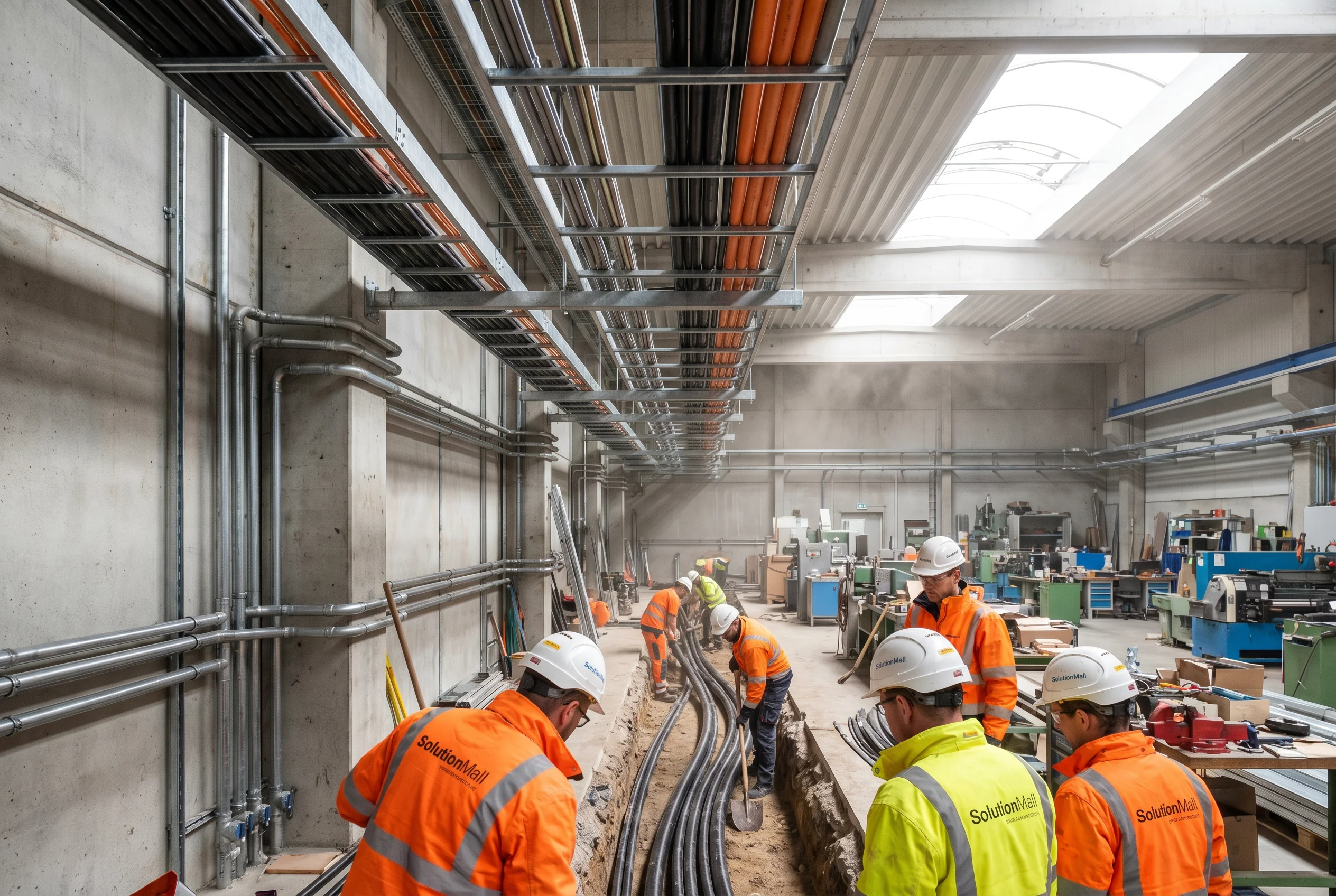
The same cable has different current-carrying capacity (ampacity) depending on how it is installed. Grouping cables together, enclosing them in conduit, or burying them in soil all reduce heat dissipation and require derating of the nominal ampacity.
Always apply derating calculations per IEC 60364-5-52 or the applicable national standard. Never operate a cable at more than 80% of its derated ampacity for continuous loads.
Conductor cross-section is determined by three independent criteria — current-carrying capacity, voltage drop, and short-circuit withstand. The largest cross-section required by any of the three criteria governs the final selection.
The conductor must carry the design current continuously without exceeding the maximum conductor temperature. Ampacity is determined by the conductor material (copper or aluminum), cross-section, insulation type, and installation conditions. After applying all derating factors, the derated ampacity must exceed the design current.
Voltage drop along the cable reduces the voltage available at the load. Excessive voltage drop causes motors to overheat, lighting to flicker, and sensitive equipment to malfunction. Most standards limit voltage drop to 3–5% of nominal voltage for final circuits and 1–2% for distribution circuits.
During a fault, the cable must withstand the short-circuit current for the duration of protective device operation without thermal damage. The minimum conductor cross-section for short-circuit withstand is calculated from the prospective fault current and the clearing time of the upstream protection device.
Both copper and aluminum are used as power cable conductors. The choice involves a trade-off between electrical performance, weight, cost, and installation practicality.
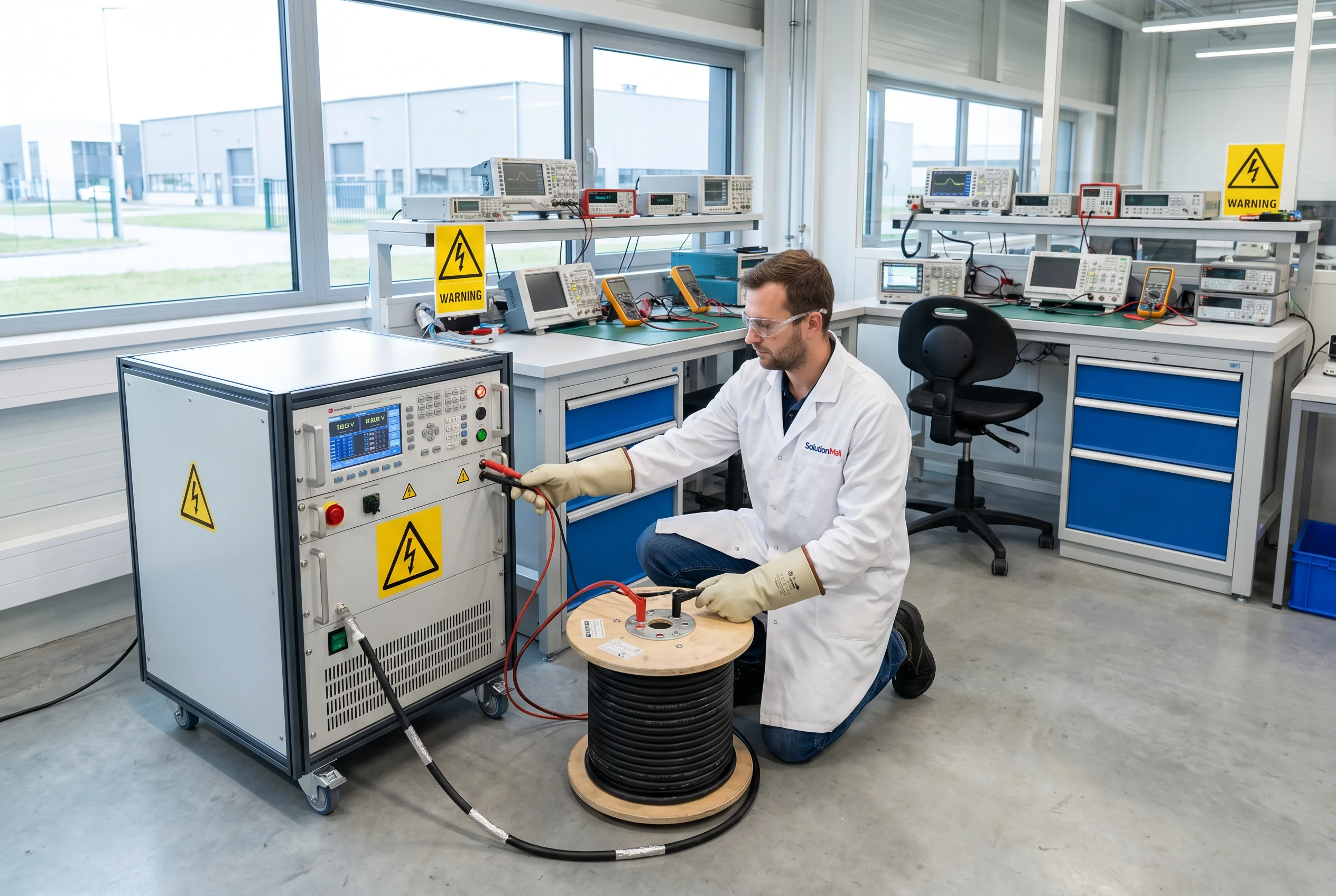
Cable standards define minimum requirements for electrical performance, fire behavior, mechanical construction, and test methods. The applicable standard depends on the project location, end-use sector, and client specification. Selecting a cable that meets the wrong standard can result in project rejection and costly replacement.
International Electrotechnical Commission. The most widely adopted framework globally, used as the basis for most national standards outside North America.
Underwriters Laboratories and the National Electrical Code. Mandatory for projects in North America (USA, Canada) and required by many multinational clients.
British Standards. Required for UK projects and widely specified in Middle East, Southeast Asia, and Commonwealth countries.
Chinese national standards (Guobiao). Mandatory for projects in China and increasingly adopted in Belt and Road Initiative countries.
IEC and GB standards are broadly harmonized for most cable types. However, UL and BS standards have significant differences in test methods, conductor class definitions, and fire performance classifications. Always confirm the applicable standard with the project engineer or authority having jurisdiction (AHJ) before procurement.
The majority of cable system failures are not caused by manufacturing defects — they result from incorrect selection, improper installation, or mismatched accessories. Understanding these failure patterns is the most effective way to prevent them.
Using a 0.6/1kV cable in a 6kV or 10kV system. The insulation breaks down within months, causing arc flash, fire, and potential fatalities. This is the single most dangerous cable selection error.
Installing standard PVC cables in public buildings, tunnels, data centers, or hospitals where LSZH or fire-resistant cables are mandated by code. Non-compliant cables fail fire inspections and, more critically, endanger lives during fire events.
Over 60% of cable system failures occur at joints and terminations — not in the cable body itself. Using generic or incompatible accessories on MV cables causes partial discharge at the interface, leading to progressive insulation failure.
Selecting conductor cross-section based only on nominal ampacity tables without applying derating factors for grouping, ambient temperature, and installation method. Undersized cables run hot, accelerate insulation aging, and trip protection devices under normal load.
Cable procurement cost is typically only 20–30% of the total lifecycle cost. Maintenance, downtime, and replacement costs over a 20–30 year service life far exceed the initial purchase price. Choosing a larger conductor cross-section reduces energy losses and extends service life.
Procuring IEC-standard cables for a project requiring UL listing, or GB-standard cables for a project specifying BS compliance. Even if the electrical performance is equivalent, non-compliant cables will fail third-party inspection and require costly replacement.
Our engineering team provides free technical consultation, system design review, and customized cable selection recommendations for your specific project requirements.